4.1 THE BASIC THRUST CHAMBER ELEMENTS
The thermodynamic processes governing the generation of thrust within a thrust chamber have been treated in chapter I. The primary function of the thrust chamber is to convert the energy of propellants into thrust. In a liquid bipropellant rocket engine, this process is characterized by the following basic functional steps:
- The liquid propellants, at their proper mixture ratio, are injected into the combustion chamber through orifices in an injector, as jets at velocities ranging from 20 to 150 feet per second. These jets either impinge to form a mixed droplet spray, or run straight into the chamber hot gas as a series of droplets. Part of the combustion reaction may already take place in the liquid state.
- The droplets are subsequently vaporized by heat transfer from the surrounding gas. The size and velocity of the droplets change continuously during their entrainment in the combustion gas flow.
- The vaporized propellants are mixed rapidly, further heated and promptly reacted at their stoichiometric mixture ratio where ever they are formed, thus effecting a continuous increase of the gaseous mass flow rate within the combustion chamber. This gas reaction is further aided by the high-speed diffusion of active molecules or atoms. The combustion is essentially complete upstream of the chamber throat, when all liquid droplets have been vaporized. Under certain conditions, shock and detonation waves may be generated by local disturbances in the combustion front, possibly caused by instability of mixing process and propellant flow prior to reaction. These effects may trigger sustained pressure oscillations at certain frequencies within the thrust chamber, resulting in destructive combustion instability. A major portion of the design and development effort, therefore, is directed toward achievement of stable combustion.
- As the gaseous products of the combustion process pass toward and through the throat, they are accelerated to sonic, and then to supersonic, velocities within the diverging nozzle section, and are finally ejected to the rear.
The basic elements of a thrust chamber required for its function, include a combustion chamber section, an expansion nozzle section, an injector, an ignition device (for nonhypergolic propellant combinations), propellant inlets and distributing manifolds, and interconnecting surfaces for, component and thrust mounts. The construction of the various thrust chamber elements depends largely on their specific operational function. However, low weight and simplicity, which make manufacturing easier, are two important factors to be considered at all times.
Figures 4-1 and illustrate a typical liquid bipropellant rocket engine thrust chamber assembly. The illustrated thrust chamber assembly is composed of four major subassemblies or basic elements; namely, thrust chamber body, injector, liquid oxygen dome, and igniter.
The thrust chamber body subassembly is of a venturi shape, consisting of a cylindrical section in which the combustion occurs; a section narrowing toward a throat; and a bell-shaped, expanding nozzle section throug' which the combustion gases are expelled (fig. 4-1). The body wall of this chamber is constructed of nickel tubes running longitudinally, joined by silver brazing, and retained by external tension bands. The tubes, of 0.012 -inch wall thickness, are of rectangular cross section of varying area, to conform to the thrust chamber shape. This construction permits simple thrust chamber cooling during operation, by flowing fuel through the tubes which form the chamber wall. The fuel, under pressure, enters the thrust chamber body at the fuel manifold inlet and is distributed to alternate thrust-chamber tubes. It then flows down toward the thrust chamber nozzle exit where the fuel return manifold reverses the flow
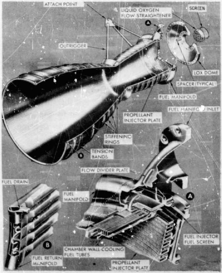 Figure 4-1.-Thrust chamber assembly.
into the return tubes. The fuel then flows through an injector fuel screen into the radial injector passages, and finally through the fuel injector orifices into the thrust chamber combustion zone. The fuel manifolds of this chamber are made of 4130 steel or 347 stainless steel. Other structural members, such as tension bands, stiffening rings, and outriggers were all made of 4130 steel. The oxidizer (liquid oxygen) enters the LOX dome under pressure through a screened central port and is distributed within the dome directly to the liquid oxygen passages and orifices (fig. 4-2).
The following are the operating characteristics and principal dimensions of a hypothetical thrust chamber similar to the one shown in figure 4-1:
- Propellants . . . . . . . . . . . . . . . . . . . LOX/RP-1
- mixture ratio . . . . . . . . . . . . . . . . 2.30
- Characteristic velocity, , ft/sec .... 5400
- Thrust coefficient, (sea level) . . . . 1.489
- Specific impulse ( ) tc (sea level), sec. . . . . . . . . . . . . . . . . . . . . . . . . . . 249
- Total propellant flow rate,
- Thrust (sea level), lb ............... . 100000
- Chamber pressure (injector end), psia . 520
- Chamber pressure (nozzle stagnation), psia.............................. . 480
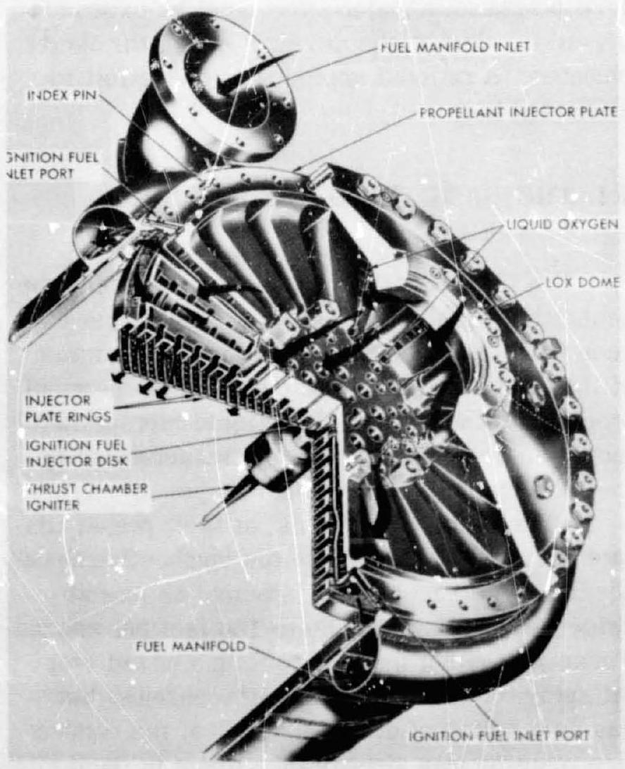 Figure 4-2.--Thrust chamber injector.
- Average gas specific heat ratio ( ) . . . 1.233
- Combustion chamber cross-section area, (at injector)
- Throat area, . . . . . . . . . . . . . . . . . 140
- Nozzle exit area, in . . . . . . . . . . . . . . . 1120
- Combustion chamber volume, (above the throat)
- Combustion chamber length, in ....... 28.5 (injector to throat)
- Characteristic chamber length, , in .38
- Overall thrust chamber length, in ..... 73
- Design contraction area ratio,
- Design expansion area ratio, . .
The thrust chamber injector (fig. 4-2) is a round plate, honeycombed with circular and radial inner passages, leading to drilled orifices. It is constructed of 4130 steel with nickel-plated surfaces, and held in position at the fuel manifold below the liquid oxygen dome with high-strength bolts. The seals between injector and thrust chamber body are of the 0 -ring type, made of rubver selected for compatibility with the fuel (RP-1). A threaded hole is provided in the center of the injector face to permit pyrotechnic thrust chamber igniter installation. The injector has 20 circular concentric copper rings which contain the injection orifices and are fed from the main propellant systems. Fuel and oxidizer are kept separate by an elaborate distribution system, feeding alternate rings. Fuel flows through the outermost ring, through each alternate inner ring, and through a central fuel disk which is separately fed from an igniter fuel valve through an ignition fuel inlet port. Liquid oxygen emerges from the remaining rings. The injection orifices are so angled that the propellants impinge in the thrust-chamber combustion zone in a like-on-like pattern (liquid oxygen on liquid oxygen and fuel on fuel). The primary orifices are arranged in pairs, with a 0.416 -inch distance between centerlines and a included impingement angle, for both propellants. In other designs, impingement angles or orifice separations are made different for the two propellants, so as to effect their impingement in different planes (multiplanar impingement as opposed to uniplanar).
The liquid oxygen dome is a single-piece, 2014-T6 aluminum-alloy die forging. It provides the inlet for the liquid oxygen. It also serves as the thrust-chamber-to-vehicle attachment interface. The flanges of the liquid oxygen dome and the injector are sealed by a spiral-wound gasket made of 304 stainless-steel strips with asbestos fillers. This type of gasket is designed specifically for cryogenic and elevated-temperature applications.
The electrically fired pyrotechnic igniter is secured centrally to the injector surface by means of a threaded joint. It is designed for one start only and must be replaced after each firing. It receives an electrical firing signal from wires connected through the nozzle exit.